Shooting rays #
How do we shoot a rays into our scene given a perspective matrix?
Assume that our virtual film plane is \(800\) by \(600\) pixel in size. This means that raster coordinates range from \([0,800] \times [0,600]\) . The positive x-axis goes form left to right and the positive y-axis goes from top to bottom. The top left corner has the raster coordinates \((0,0)\) and the right bottom has the raster coordinates \((800,600)\) . The virtual camera is located at \((0,0,0)\) and looks at \((0,0,100)\) . The up vector of the camera is \((0,1,0)\) . The horizontal FOV is \(30°\) . Let the near clip plane distance be \(100\) and far clip distance \(500\) .
We want to compute for each pair of raster coordinates a corresponding ray. The raster coordinate \((400,300)\) (center of virtual film plane) should give us a ray in world space with origin \((0,0,0)\) and direction \((0,0,1)\) .
If we change the position and look at point of the camera an keep the other parameters we come up with the following simple test cases:
| Test Case Index | Camera Position | Camera Look At | FOV | near clip plane distance | far clip plane distance | Film Plane Size in Pixels (width, height) | Raster position | Expected ray origin | Expected center ray direction |
|---|---|---|---|---|---|---|---|---|---|
| 0 | \((0, 0, 0)\) | \((0,0,100)\) | 30° | \(100\) | \(500\) | \(800 \times 600\) | \((400,300)\) | \((0, 0, 0)\) | (0,0,1) |
| 1 | \((0,0,10)\) | \((0,0,100)\) | 30° | \(100\) | \(500\) | \(800 \times 600\) | \((400,300)\) | \((0,0,10)\) | (0,0,1) |
| 2 | \((0, 0, 0)\) | \((45,0,45)\) | 30° | \(100\) | \(500\) | \(800 \times 600\) | \((400,300)\) | \((0, 0, 0)\) | \((\sqrt{0.5}, 0, \sqrt{0.5})\) |
| 3 | \((0,0,0)\) | \((100,0,0)\) | 30° | \(100\) | \(500\) | \(800 \times 600\) | \((400,300)\) | \((0,0,0)\) | \((1,0,0)\) |
| 4 | \((0,0,0)\) | \((100,100,100)\) | 30° | \(100\) | \(500\) | \(800 \times 600\) | \((400,300)\) | \((0,0,0)\) | \((\sqrt{\frac{1}{3}}, \sqrt{\frac{1}{3}}, \sqrt{\frac{1}{3}})\) |
| 5 | \((0,0,0)\) | \((-100,-100,-100)\) | 30° | \(100\) | \(500\) | \(800 \times 600\) | \((400,300)\) | \((0,0,0)\) | \((-\sqrt{\frac{1}{3}}, -\sqrt{\frac{1}{3}}, -\sqrt{\frac{1}{3}})\) |
Considering test case 0 again. What happens if we choose different raster coordinates, e.g. \((0,300)\) ? If we change the FOV to \(90°\) it becomes pretty easy. The direction vector of the ray should be \((-\sqrt{0.5}, 0, \sqrt{0.5})\) . This helps us to extend our test cases:
| Test Case Index | Camera Position | Camera Look At | FOV | near clip plane distance | far clip plane distance | Film Plane Size in Pixels (width, height) | Raster position | Expected ray origin | Expected center ray direction |
|---|---|---|---|---|---|---|---|---|---|
| 6 | \((0, 0, 0)\) | \((0,0,100)\) | 90° | \(100\) | \(500\) | \(800 \times 600\) | \((0,300)\) | \((0, 0, 0)\) | \((-\sqrt{0.5}, 0, \sqrt{0.5})\) |
| 7 | \((0, 0, 0)\) | \((0,0,100)\) | 90° | \(100\) | \(500\) | \(800 \times 600\) | \((600,300)\) | \((0, 0, 0)\) | \((\sqrt{0.5}, 0, \sqrt{0.5})\) |
How do we get from raster space to normalized device coordinates (NDC)? The following table lists expected NDC coordinates for given raster space coordinates:
| Raster space coordinates | Film Plane Size in Pixels (width, height) | Expected NDC coordinates |
|---|---|---|
| \((0,0,0)\) | \(800 \times 600\) | \((-1,1,0)\) |
| \((0,300,0)\) | \(800 \times 600\) | \((-1,0,0)\) |
| \((0,600,0)\) | \(800 \times 600\) | \((-1,-1,0)\) |
| \((400,300,0)\) | \(800 \times 600\) | \((0,0,0)\) |
The Matrix \(M_{\textsf{RasterSpaceToNDC}}\) that transform raster space coordinates to normalized device coordinates looks like this (where \(w\) and \(h\) are the width and height of the film plane in pixels):
\(M_{\textsf{RasterSpaceToNDC}} = T(-1, -1, 0) \cdot S(2, 2, 1) \cdot T(0,1,0) \cdot S(1,-1,1) \cdot S(\frac{1}{w},\frac{1}{h},1)\)Here is how to derive it. First we go from raster space to normalized raster space.

In the next step we flip the y axis. That means a value of \(0\) is mapped to \(1\) or for instance \(0.3\) is mapped to \(0.7\) . That means \(y'= h - y = 1-1y\) . This flip can be expressed by a scale and translation matrix. First we do the scale with \(S(1-1,1)\) and we apply the translation \(T(0,1,0)\)

In the last step we scale by \(S(2,2,1)\) and translate by \(T(-1,-1,0)\) and end up with normalized device coordinates.

Assuming that our projection matrix is \(P\) and we have squared film plane a point is transformed from raster space to camera space by:
\(P^{-1} \cdot M_{\textsf{RasterSpaceToNDC}}\)If the film plane is not a square and when considering the FOV has a horizontal field off view a point the transformation that tranform a raster space point to a 3D point in camera space looks like this ( \(\textsf{aspect} = \frac{w}{h} \) ):
\(P^{-1} \cdot S(1, \frac{1}{aspect}, 1) \cdot M_{\textsf{RasterSpaceToNDC}}\)Note transforming from NDC to camera space happens by multiplying with \(P^{-1}\) . This will shift the z-coordinate form \(0\) to the near clipping plane distance. If a raster space point is tranformed to the camera sapace point it can be interpreted as a direction vector. This is one way how we can shoot ray in a ray tracer. The perspective projection matrix transforms the camera frustum to clip space (e.g. \([-1,1] \times [-1,1] \times [0,1]\) ). For instance a point on the far clip plane can be after perspective projection something like \((0, 0, 500, 500)\) which is equal to \((0,0,1)\) .
Lets consider how Nori shoots rays. By the way I did some small modifications to the source code to get this working for a left-handed coordinate system.
/**
  * Translation and scaling to shift the clip coordinates into the
  * range from zero to one. Also takes the aspect ratio into account.
  */
m_sampleToCamera = Transform(
    Eigen::DiagonalMatrix<float, 3>(Vector3f(0.5f, -0.5f * aspect, 1.0f)) *
    Eigen::Translation<float, 3>(1.0f, -1.0f/aspect, 0.0f) * perspective).inverse();

...

/* Compute the corresponding position on the
    near plane (in local camera space) */
Point3f nearP = m_sampleToCamera * Point3f(
    samplePosition.x() * m_invOutputSize.x(),
    samplePosition.y() * m_invOutputSize.y(), 0.0f);
Going from raster space coordinates to normalized raster space happens via samplePosition.x() * m_invOutputSize.x(), samplePosition.y() * m_invOutputSize.y().
The perspective matrix is also inverted,
and in the inverted transform (m_SampleToCamera) the last operation.
This brings us to the conclusion:
\(S(1, \frac{1}{\textsf{aspect}}, 1) \cdot T(-1, -1, 0) \cdot S(2, 2, 1) \cdot T(0,1,0) \cdot S(1,-1,1) =\) \((S(0.5, -0.5 \cdot \textsf{aspect}, 1) \cdot T(0.5, 0.5 \cdot \textsf{aspect}, 0))^{-1}\)
Assuming \(\textsf{aspect}=1\) . The above equation is correct.
Prove for other aspect ratios: We can try to get rid of the aspect: \( (S(0.5, -0.5 \cdot \textsf{aspect}, 1) \cdot T(0.5, 0.5 \cdot \textsf{aspect}, 0))^{-1} =\) \( (S(0.5, -0.5, 1) \cdot T(0.5, 0.5, 0) \cdot S(1, \textsf{aspect}, 1))^{-1}\)
Now we have only to show that \((S(0.5, -0.5, 1) \cdot T(0.5, 0.5, 0))^{-1} = T(-1, -1, 0) \cdot S(2, 2, 1) \cdot T(0,1,0) \cdot S(1,-1,1)\)
What we did already for \(\textsf{aspect} = 1\) .
Usually ray has a minimal and a maximal scalar parameter value, that describes where a ray starts and where it ends. Those values should be set to the near and far clipping plane for camera rays correspondingly. The values are different for different rays since the distance to the near and far clipping plane depends on the ray direction.

The minimal and maximal distance of the ray can be computed by:
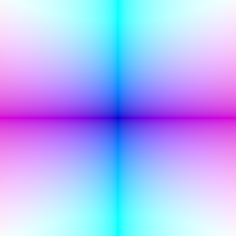
\(t_{min}=\frac{1}{z_d} \cdot n\) \(t_{max}=\frac{1}{z_d} \cdot f\)The following image shows for an image plane of \(800 \times 800\) and a FOV of \(90°\) the absolute values of the normalized camera ray directions:
From raster space to inverted raster space #
Sometimes when working with discrete raster coordinates and can be usefull if the y-axis is filipped (I call this inverted raster space).

Flipping happens by \(\) y = height - y - 1 \(\)
Or in other words:
First scale by \(S(1,-1,1)\) and then translate by \(T(0,\textsf{height}-1,0)\)
Further testing #
The table shown above can be turned into tests. Also the image that shows the ray directions can be used within an automated test.
Another idea to test ray shooting can look like this:
TEST_F(Sensor3fTest, RayDirections2) {
    // Arrange
    float angle = 30.f;
    sensor.setTransform(rotateZ(degreeToRadian(angle)));
    Point2f sample_position{film_plane_size_in_pixels.x() / 2.f, film_plane_size_in_pixels.y() / 2.f};

    // Act
    Ray3f ray = sensor.generateRay(sample_position);

    // Assert
    Vector3f expectedRayDir = rotateZ(degreeToRadian(angle)) * Vector3f{.0f, .0f, 1.f};

    EXPECT_THAT(ray.direction.x(), expectedRayDir.x());
    EXPECT_THAT(ray.direction.y(), expectedRayDir.y());
    EXPECT_THAT(ray.direction.z(), expectedRayDir.z());
}